new pcb 2.
So the PCBs arrived.
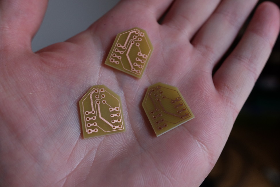
attiny breakout
This is just a small breakout board for 8-pin attinys that plugs into breadboard. It has ICSP pin header for connecting AVR programmer.
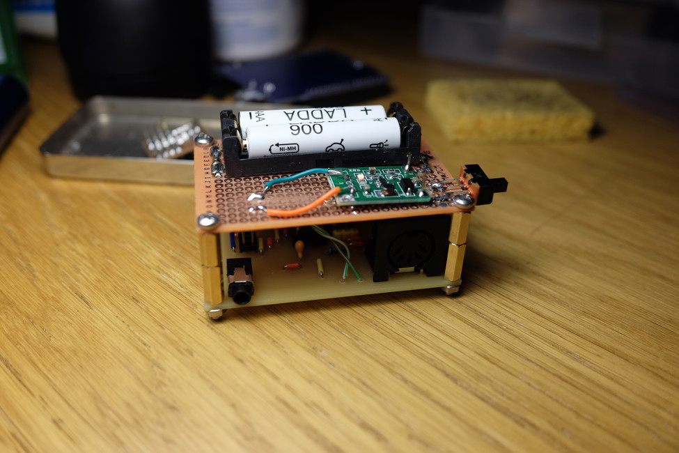
MIDI-to-CV
I put it together, it worked on the first try. Here are some things I have to change for the next revision:
- potentiometer hole should be oval and bigger (consult datasheet)
- audio jack should have larger pads, because the drill almost erased them
- The mount holes I really wanted were M2, not M3. But I already bought M3 screws, so I carefully enlarged the holes on the perfboard with a drill to be M3 as well.
I soldered the boost conveter to a perfboard and mounted it atop of the MIDI-to-CV board. The whole structure has a nice heft to it.
The only thing left to do now is to make the box.
Updated sources and schematics for revision 3.
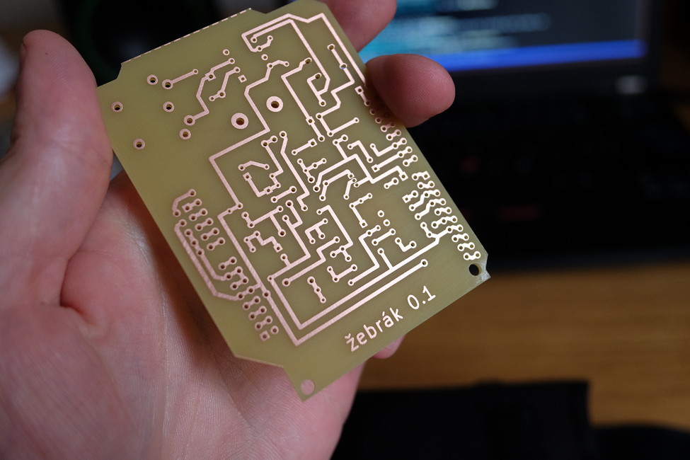
žebrák filter
This was such a clusterfuck.
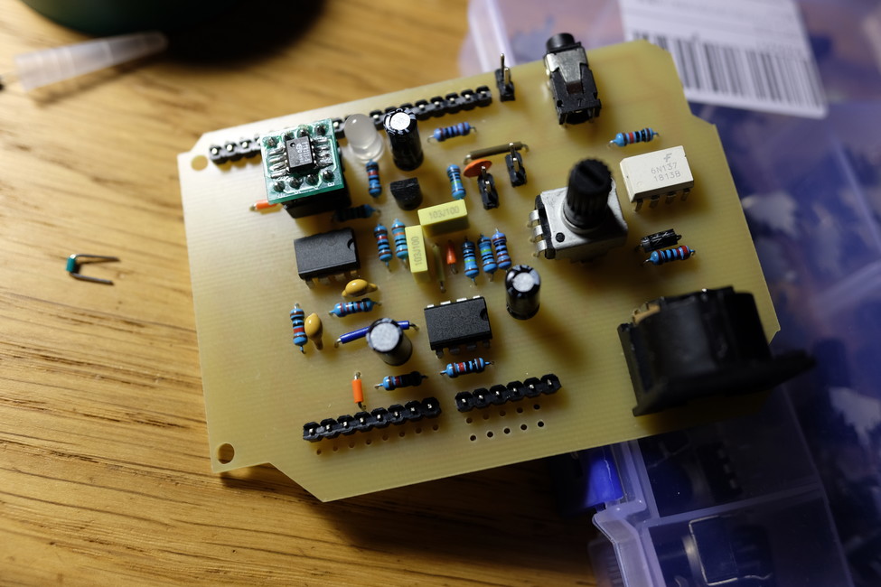
I didn't have 8-pin IC sockets and I was eager to try it out on the day it came in, so I soldered the op-amps directly to the PCB (mistake #1; also: why didn't I think of chopping larger IC sockets into smaller ones?).
The digital part worked fine, but the analog did not. In order to debug it, I had to desolder the op-amps. I still don't have oscilloscope, so I tried to listen for audio signal with headphones instead. I bypassed the filter section completely and made the op-amp into a buffer, but it still wouldn't work. Then I found out the op-amp was overheating, but I couldn't find any shorts or things that would be the cause for that.
Later I remembered that the circuit that I breadboarded (that worked) wasn't the same as the one I made PCB for (mistake #2).
So... utter fail. I have to revisit this project later.
Things to change in the future:
- pt8211 on adapter doesn't fit into the socket (holes too small)
- filter circuit doesn't work