new PCBs
Yesterday I sent two new PCBs to manufacturer - one was a revision of MIDI-to-CV, the other one was low-pass filter board for my synth "žebrák" (actually it is just Arduino shield with filter and MIDI port and pin-sockets and few other things so I can use it for prototyping of other ideas).
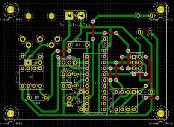
MIDI-to-CV
For the MIDI-to-CV layout I decided to use old-school DIY design approach - single layer, fat traces (35 mil), wire connections on the flip-side and everything positioned on a 100 mil grid. The grid layout was to make it possible to design in on paper first. It also fixed my problem with selecting footprints, because now if something has length 3 grid dots, its footprint has length 3 * 2.54 mm = 7.62 mm etc.
Another change was that I added mounting holes for M3 screws. The board dimensions and position of holes is actually to match a generic 7 cm * 5 cm perfboard. I plan to use the perfboard as a "shield" with power switch, battery pack and a boost converter to provide power to the MIDI-to-CV board bellow it. And I removed the DC power jack.
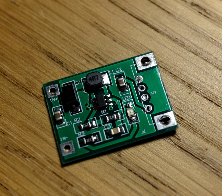
The boost converter is actually a small PCB board from aliexpress (sold under the name "USB power bank charger step-up"). It converts 0.9-5 V to 5 V, which is ideal for my application. I just removed the USB connector and soldered it on the perfboard.
I also made a mistake when copying the pin numbers to my notebook and I layouted it that way. But everything was layed out neatly, and I didn't want to have to do it again, so I kept it. And now I have to fix this in software and basically make another one, incompatible version of MIDI-to-CV firmware with different pin assignment. I'm dumb.
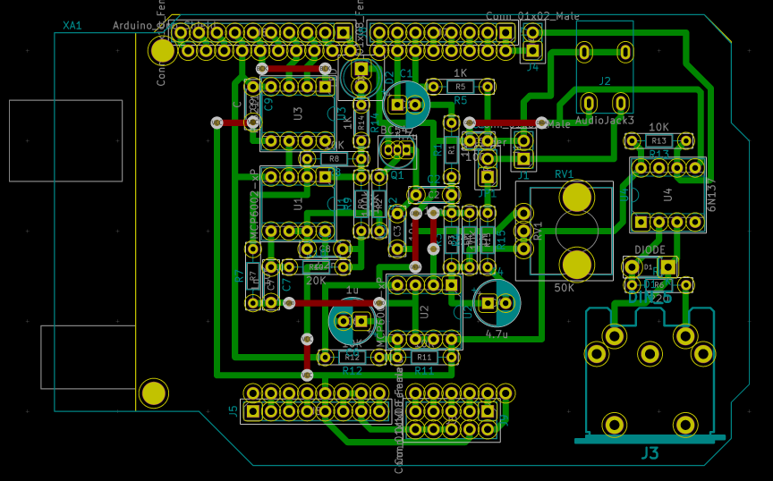
žebrák filter shield
This is from another project - Arduino synth with analog filter. It was made as an Arduino shield with some additional goodies thrown in - output audio jack, MIDI input, pin header with analog pins to connect panel with muxed knobs later, etc.
The filter itself is a resonant peaking filter very much like old analog drum machines use and can be controlled by voltage with one additional transistor. It can be found either in Meeblip triode or under the name simplest VCF on earth.
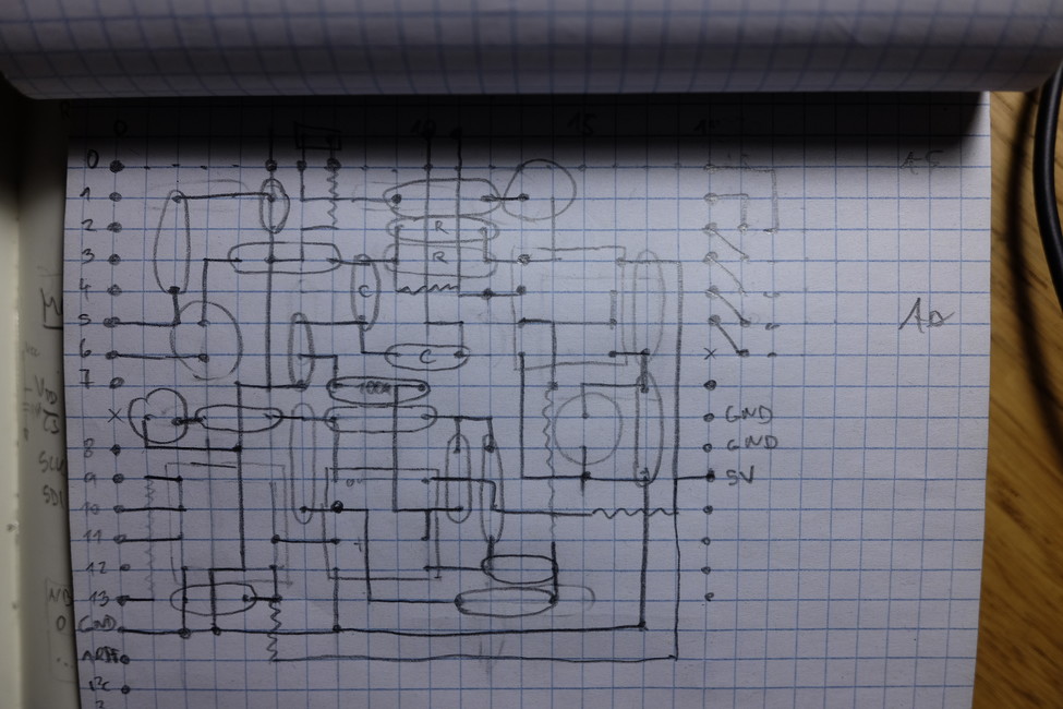
I layouted it on paper during a long train journey together with the MIDI-to-CV board. I copied it to KiCad later. I even found an Arduino shield footprint... and thanks god for that actually. Because what I didn't notice earlier was - Arduino sockets are not laid on 100 mil grid, even though the sockets itself are 100 mil. There's a 160 mil gap between the sockets!
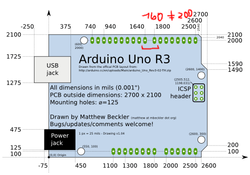
No wonder that the perfboard shield I did looked bent from one side (I had no idea why it did that and assumed it was because of bent pins).
anyway
Let's wait and see what comes from the manufacturer. I'll try to find a suitable oscilloscope in the meantime.