new pcb 2.
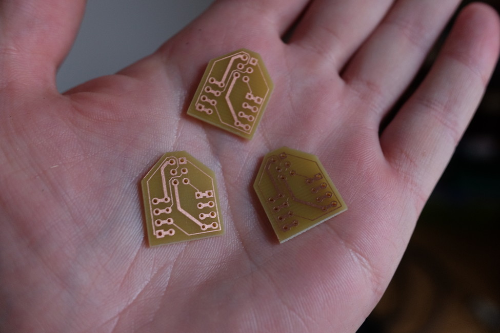
So the PCBs arrived.
attiny breakout
This is just a small breakout board for 8-pin attinys that plugs into breadboard. It has ICSP pin header for connecting AVR programmer.
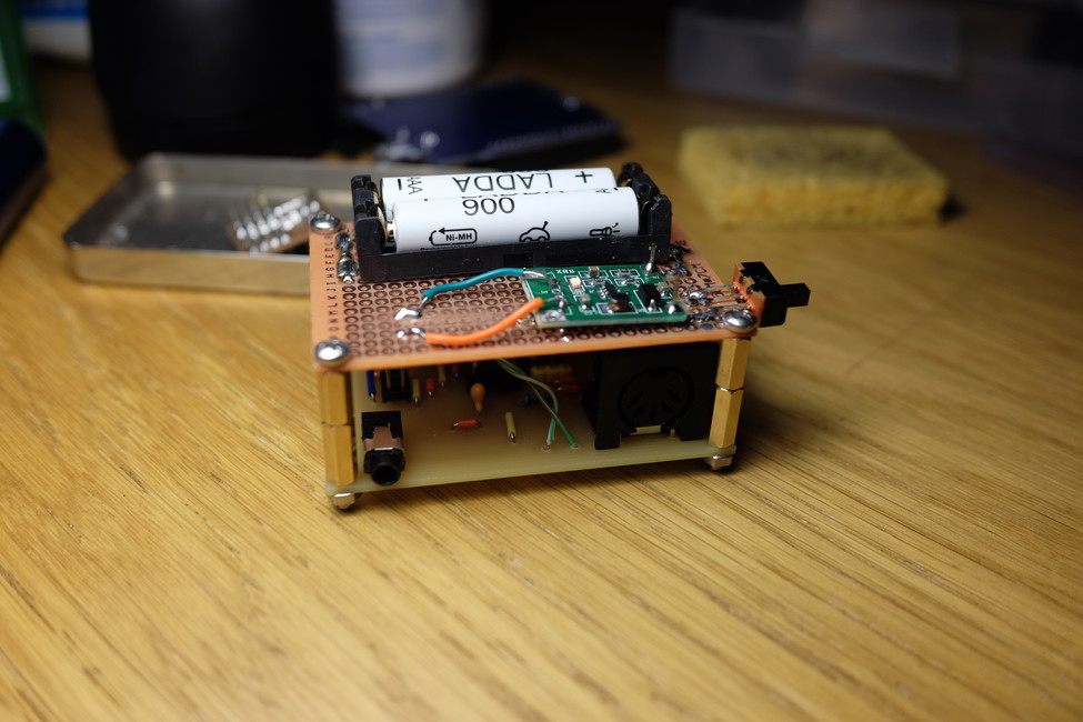
MIDI-to-CV
I put it together, it worked on the first try. Here are some things I have to change for the next revision:
- potentiometer hole should be oval and bigger (consult datasheet)
- audio jack should have larger pads, because the drill almost erased them
- The mount holes I really wanted were M2, not M3. But I already bought M3 screws, so I carefully enlarged the holes on the perfboard with a drill to be M3 as well.
I soldered the boost conveter to a perfboard and mounted it atop of the MIDI-to-CV board. The whole structure has a nice heft to it.
The only thing left to do now is to make the box.
Updated sources and schematics for revision 3.
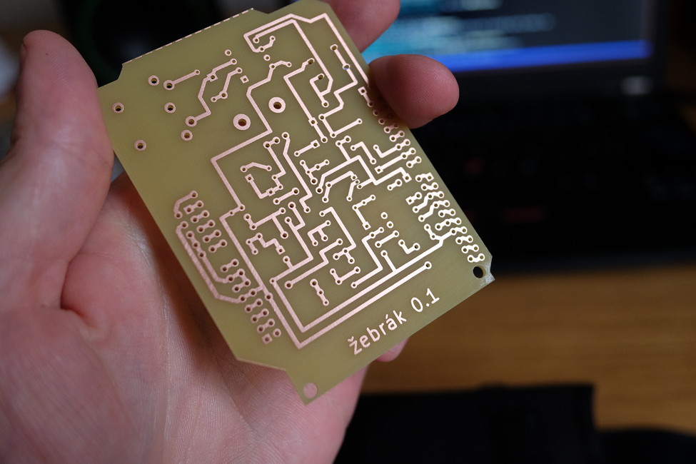
žebrák filter
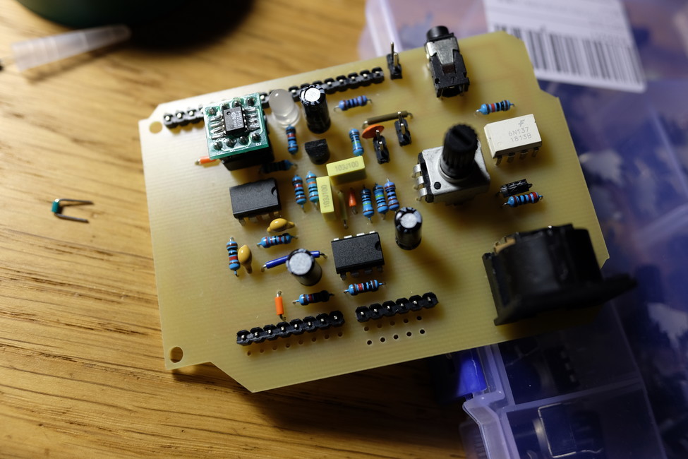
This was such a clusterfuck.
I didn't have 8-pin IC sockets and I was eager to try it out on the day it came in, so I soldered the op-amps directly to the PCB (mistake #1; also: why didn't I think of chopping larger IC sockets into smaller ones?).
The digital part worked fine, but the analog did not. In order to debug it, I had to desolder the op-amps. I still don't have oscilloscope, so I tried to listen for audio signal with headphones instead. I bypassed the filter section completely and made the op-amp into a buffer, but it still wouldn't work. Then I found out the op-amp was overheating, but I couldn't find any shorts or things that would be the cause for that.
Later I remembered that the circuit that I breadboarded (that worked) wasn't the same as the one I made PCB for (mistake #2).
So... utter fail. I have to revisit this project later.
Things to change in the future:
- pt8211 on adapter doesn't fit into the socket (holes too small)
- filter circuit doesn't work
new PCBs
Yesterday I sent two new PCBs to manufacturer - one was a revision of MIDI-to-CV, the other one was low-pass filter board for my synth "žebrák" (actually it is just Arduino shield with filter and MIDI port and pin-sockets and few other things so I can use it for prototyping of other ideas).
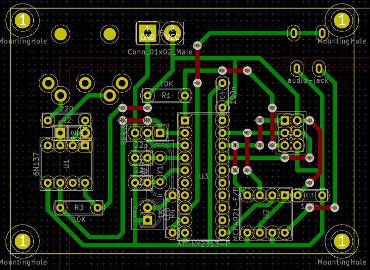
MIDI-to-CV
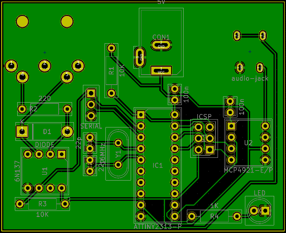
For the MIDI-to-CV layout I decided to use old-school DIY design approach - single layer, fat traces (35 mil), wire connections on the flip-side and everything positioned on a 100 mil grid. The grid layout was to make it possible to design in on paper first. It also fixed my problem with selecting footprints, because now if something has length 3 grid dots, its footprint has length 3 * 2.54 mm = 7.62 mm etc.
Another change was that I added mounting holes for M3 screws. The board dimensions and position of holes is actually to match a generic 7 cm * 5 cm perfboard. I plan to use the perfboard as a "shield" with power switch, battery pack and a boost converter to provide power to the MIDI-to-CV board bellow it. And I removed the DC power jack.
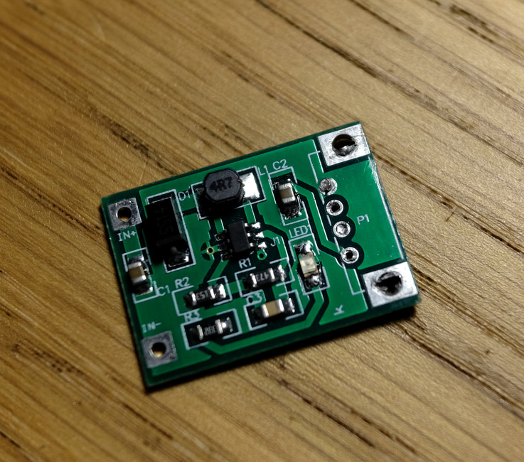
The boost converter is actually a small PCB board from aliexpress (sold under the name "USB power bank charger step-up"). It converts 0.9-5 V to 5 V, which is ideal for my application. I just removed the USB connector and soldered it on the perfboard.
I also made a mistake when copying the pin numbers to my notebook and I layouted it that way. But everything was layed out neatly, and I didn't want to have to do it again, so I kept it. And now I have to fix this in software and basically make another one, incompatible version of MIDI-to-CV firmware with different pin assignment. I'm dumb.
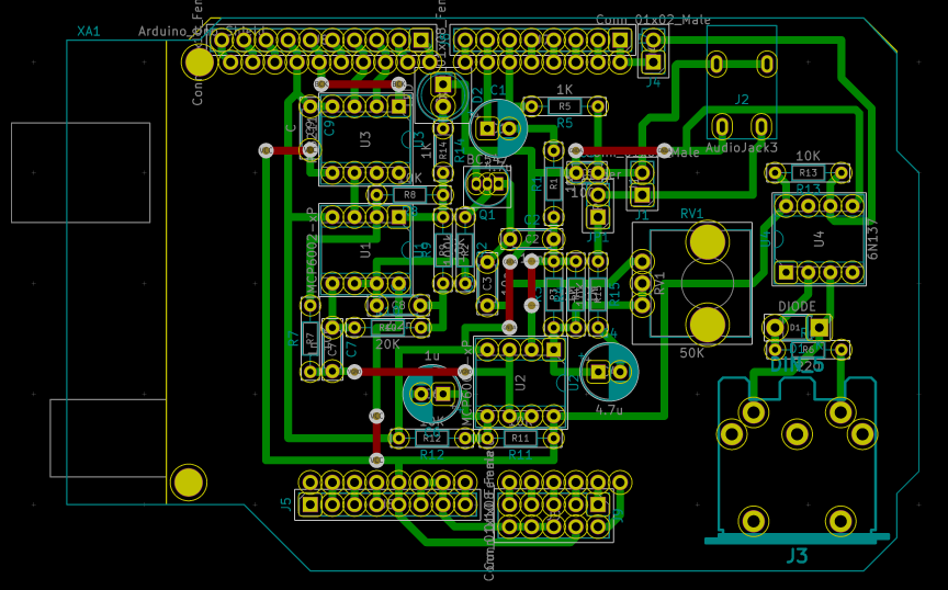
žebrák filter shield
This is from another project - Arduino synth with analog filter. It was made as an Arduino shield with some additional goodies thrown in - output audio jack, MIDI input, pin header with analog pins to connect panel with muxed knobs later, etc.
The filter itself is a resonant peaking filter very much like old analog drum machines use and can be controlled by voltage with one additional transistor. It can be found either in Meeblip triode or under the name simplest VCF on earth.
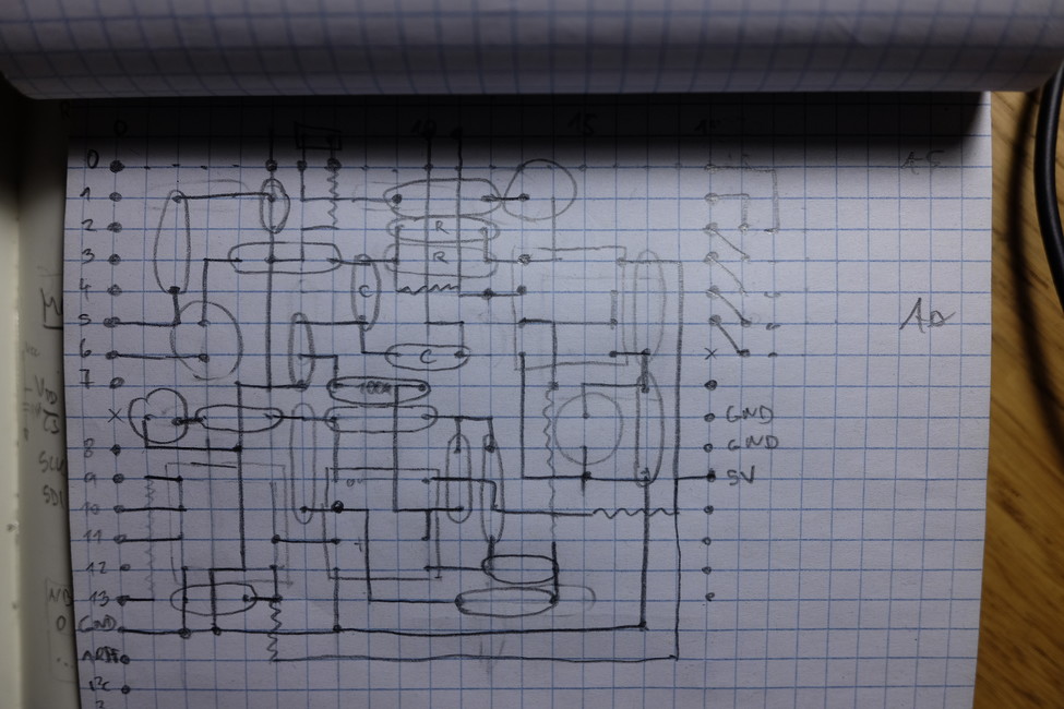
I layouted it on paper during a long train journey together with the MIDI-to-CV board. I copied it to KiCad later. I even found an Arduino shield footprint... and thanks god for that actually. Because what I didn't notice earlier was - Arduino sockets are not laid on 100 mil grid, even though the sockets itself are 100 mil. There's a 160 mil gap between the sockets!
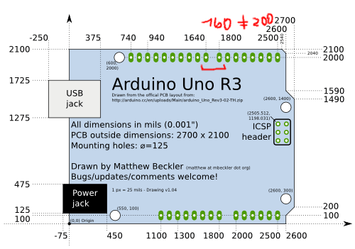
No wonder that the perfboard shield I did looked bent from one side (I had no idea why it did that and assumed it was because of bent pins).
anyway
Let's wait and see what comes from the manufacturer. I'll try to find a suitable oscilloscope in the meantime.
no content 2
No content this week either, but here are some assorted paragraphs of text.
mumu is first project (in quite some time) I haven't abandoned. I keep growing it, instead of bulldozing the whole place after a few months (to erase all my mistakes). I enjoy grooming it, rebasing it, cleaning out garbage, trimming branches... I would like to write a history article about it sometime.
But: I can't write a history article without doing research - even if it's my history. Research refreshes memory.
I like to do PCB layouts on paper. It reminds me of Tycoon Transport - connecting factories and resources with tracks. After a while, when I get really into it, I start to recognize neighborhoods around the city, I start having adventures in the midst of the components.
I can't make jokes in English - every time I try to make one it ends either in blank stares or some horrible misunderstanding.
The keypad at the entrance of our new building makes the most wonderful sound, exactly like the intro to structures by John Baker and I think it may be synthesized the same way.
I shouldn't listen to recordings I make. Or at least not repeatedly. Some of them I like and enjoy, and I get really depressed if I listen to them too much. It feels like inbreeding. I like the idea of making music for myself though (aka "Taking Drugs To Make Music To Take Drugs To").
no content
I have nothing to say.
I haven't done much since the last post. I realized that the midi-to-cv still wasn't finished: it didn't have battery holder and the PCB was sort-of ugly (trace-layout-wise).
When I was looking for a nice PT2399 delay, I found http://tonepad.com/, which has very nice pre-layouted PCBs for guitar pedals (and the schematics are done in Corel fucking Draw!). I learned few things about single-side board design from them: make wide traces, do them on 100 mil grid (same grid perfboard has), do not fear non-planarity and connect stuff with wires. And design it on paper first.
But I have this one trick with which I turn everything to work, so I was deferring the redesign up to the point I lost all interest.
Another problem: boxes and cabinets. I do not know how to do them. I was thinking about panel-drilling, laser-cutting and 3D-printing. And designing case with integrated battery holder that's integrated to PCB (like Monotron has). I want to try all of that. But I have to start with cardboard design, measuring holes, ordering screws and all that.
I used to write "ideas" of things I wanted to make. My notebook looked like graveyard of dreams. They weren't "ideas" per-se, they were just objects I wanted to have. I do not write "dreams" anymore, I keep them in a big pot in my head and I stir them like stew.
Model:Samples is overpriced piece of shit. I was thinking about it a week ago - trying to remember all the shitty gear that had similar "features". Volca Sample came to mind. Also: Korg ES-1, from the first series of Electribes. So I went and bought it, for about 135 EUR. Not bad, considering it is more powerful than both both Volca Sample and the Model:Samples (because it can actually sample).
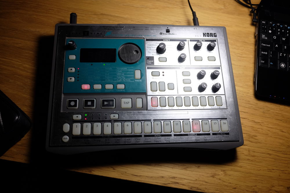
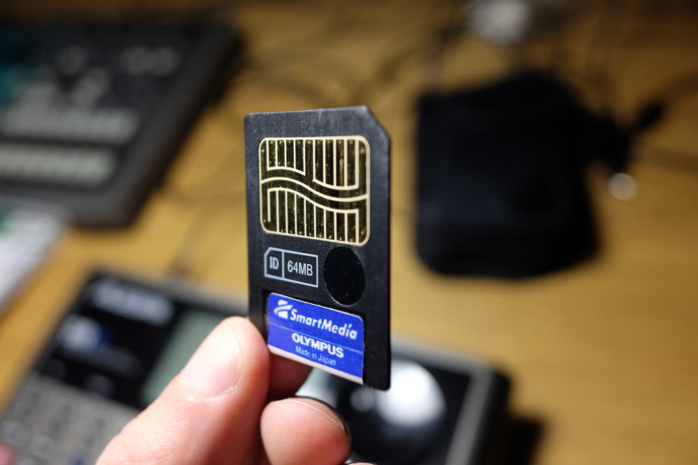
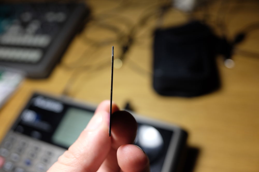
It uses Smart Media cards (I almost wrote "Smart:Media"), which are something between flash card and floppy disk (the 5.25" ones) - it's flash, but it's thin and "floppy".
I have nothing to say. I haven't even done a song on ES-1.
I have been listening to tracker jungle a lot lately.
How the hell did I manage to turn all my hobbies to something that feels like work and that I need to force through? Also: I want to try some "different" things (rust? evolutionary algorithm for fastest stick figure? web design?).
nevertheless
I want to write something at least once a week, be it a "No Content" post or something more meaningful.
pcb - part 4.
Man, what a speed! I ordered it on Saturday and got it from postman on Tuesday morning, neatly packaged and everything. It looked like this:
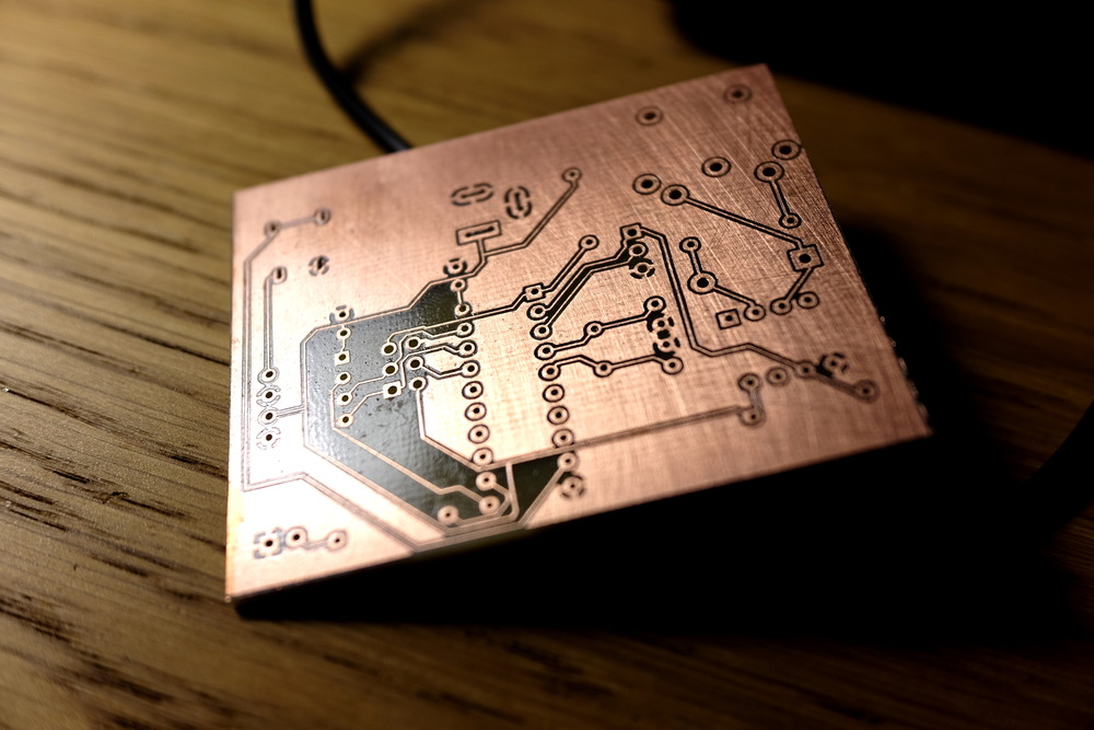
I found out I made two mistakes:
- I didn't check the "advance milling" option, so only round holes were made by the manufacturer. I had to make the oval ones myself with knife (for power jack and for audio jack). The way I was doing it I expected to cut up myself badly, but I was pleasantly surprised that I didn't.
- The traces I designed were just way too thin, at least for this kind of "basic" process without additional protective paint. The pads for soldering and the space between traces and "filled" ground is also too small. At two points a bit of solder got mixed up with some "PCB dust" and it took some work to get it off because it bridged the "fill" ground with a trace.
What really did surprise me was that when I soldered all components on, it worked on first try. Not even a hitch. And it can be programmed with ISP. Yay!
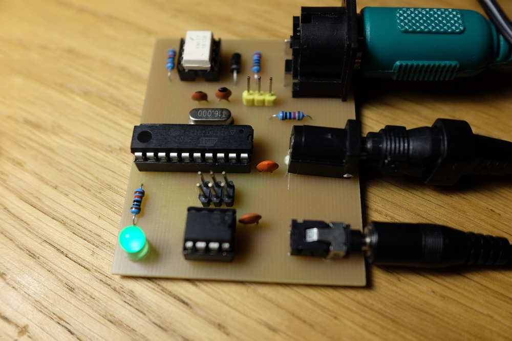
The sources for the whole project are here
pcb - part 3.
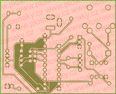
So just now I generated the gerber files and sent them to the manufacturer. This is the preview from his web:
The schematic drawing went OK at the end, considered how tired I felt at the time of the last post.
Next were the footprints - the KiCad library was missing footprint for my 3.5 mm jack connector, so I took out a ruler and started measuring its dimensions. At the end I found out that even the shittiest chinese connectors from aliexpress have a datasheet if you know the name of the component. Also some good people created footprint for DIN-5 "MIDI" connector.
Rest of the components had "standard" footprints, but it's really confusing to go looking for "standard ceramic cap" footprint or "standard resistor" footprint, because the KiCad footprint library doesn't have popularity meter next to the components and there isn't a shopkeeper that would just dutifully nod head at a request for "standard Arduino power jack".
Next went the PCB design. I found out a local PCB manufacturer that has good prices, but he cannot do "plated through-holes" - which means that the two sides of board aren't connected through the hole itself and components have to be soldered on both sides if such connection is desired.
So I designed the board to be one-sided. And it was quite a feat to get everything layed out. The planarity itself wasn't a problem, but between two pins there is usually space only for one trace. In the end I had to draw it on piece of paper to "speed up" the design, but I managed. Also, thank god for "GND copper fill".
I generated gerbers.
Fortunately before sending it off to manufacturer, I showed it to people on ##music-electronics IRC channel on Freenode and they pointed out to me few fatal errors in my design (like barrel jack pointing towards MCU instead of out etc.) which saved me one revision of PCB (thanks to dingwat and antto!).
So I sent it to manufacturer and I'm curious what comes back.
pcb - part 2.
KiCad woes.
So I had drawn a schematic on paper, found a tutorial about KiCad and started going through it.
And what a PITA this program is. Compared to KiCad, circuitjs is a pinnacle of UX design. Clearly, KiCad was designed by committee of open-source engineers (note the two EEs), who were high on exhaust fumes. But it's free so...
I've redrawn the circuit, that worked. But when I tried to assign the footprints the program kept crashing. I did google for help, but to no avail. I didn't want to spent whole evening trying to compile the program from sources and I also didn't want to upgrade from testing, so I tried KiCad from Ubuntu at work (which is 4.0.2 and not 4.0.5) and that was OK.
Also: I found out that there are backports of KiCad 5 from testing to stretch (stable).
When I watched further videos about designing the PCB I found out that it is not automated at all! You just have to drag the paths along the board by yourself (and also: I found out where the game "planarity" came from - at the beginning all the footprints are put at the same point, connected with "air wires", and you have to untangle them and arrange them along the board, with as little number of wire crossing as possible).
At this point I spent so much time with trying to get KiCad working and figuring out editor quirks it would be quicker to design it on paper and solder it on perf-board.
And I haven't yet started with footprint editor (I have to find out what kind of jacks I'll be using and their dimensions - 3.5 mm audio jacks and barrel jacks for power).
But I wanted this so let's not make it into more work that it actually is.
Next time: more PCB design.
pcb - part 1.
I was looking for a project with which I could learn how to make PCBs. My friend wanted a cheap MIDI-to-CV converter so I offered to make him one. It's a simple circuit and probably a good fit for a first PCB. It also fulfills my side-goal of using up all the components I've bought on aliexpress.
The circuit
The circuit is fairly straight-forward: signal goes as MIDI to optocoupler (6N137), then to attiny2313 as UART, then to MCP4921 DAC via SPI. Some additional things I wanted: dip-switch to set MIDI channel, ICSP 6-pin header to program the attiny (+ serial), maybe pin-header with jumpers to set what signal goes where on the TRS 3.5 mm output jack.
(TODO: try to look-up cheapest chinese no-name 8 bit MCU with serial on aliexpress and make something using it)
Problem 0
Even before I started I run into a problem when a simple LED-blinker didn't work properly. This turned out to be because I tried to call linker it without -mmcu=attiny2313 which didn't include correct linker script and caused __ctors_end section to be linked at address 0 where __vectors should have been.
This would be excusable if it hadn't happen to me at least twice before.
Problem 1: no SPI
The attiny2313 is the cheapest MCU with UART you can get in shops around here.
I've thought it had SPI controller as well, but it doesn't. Instead it has something called USI (Universal Serial Interface?), which is just a shift register with 4-bit counter. Each clock edge has to be flipped manually, but it's just single-cycle instruction, so you can reach speed up to f_osc/2, which is actually the same maximum speed you get on atmega with real SPI controller.
Problem 2: not enough space
A program containing just UART initialization and printf("hello world %d\n", 9) takes about 1570 bytes, which is just too big for an MCU with 2 KB of flash. I need a write a custom printf implementation if I want to see any debugging messages.
(If you wonder about the Hello world format string: printf("hello world\n") gets optimized to puts("hello world") and puts takes much less code than printf proper.)
Problem 3: no float
Conversion from MIDI note to linear frequency with pitch-bend is easy to write in fixed-point arithmetic, but it's even easier to write in floating-point and AVR supports soft-float well.
But the soft-float code just doesn't fit!
- with float: 2042 bytes
- in 16-bit fixed-point arithmetic: 1052 bytes
- plus my own printf: 1396 bytes
Why not Arduino?
I started rolling out my own fixed-point arithmetic and printf even before I knew library functions don't fit. I just thought it would be cooler.
How come I am that dumb?
TODO: how long would it take to to write it on Arduino? Using libraries and Arduino IDE and every shortcut I could find?
Breadboard
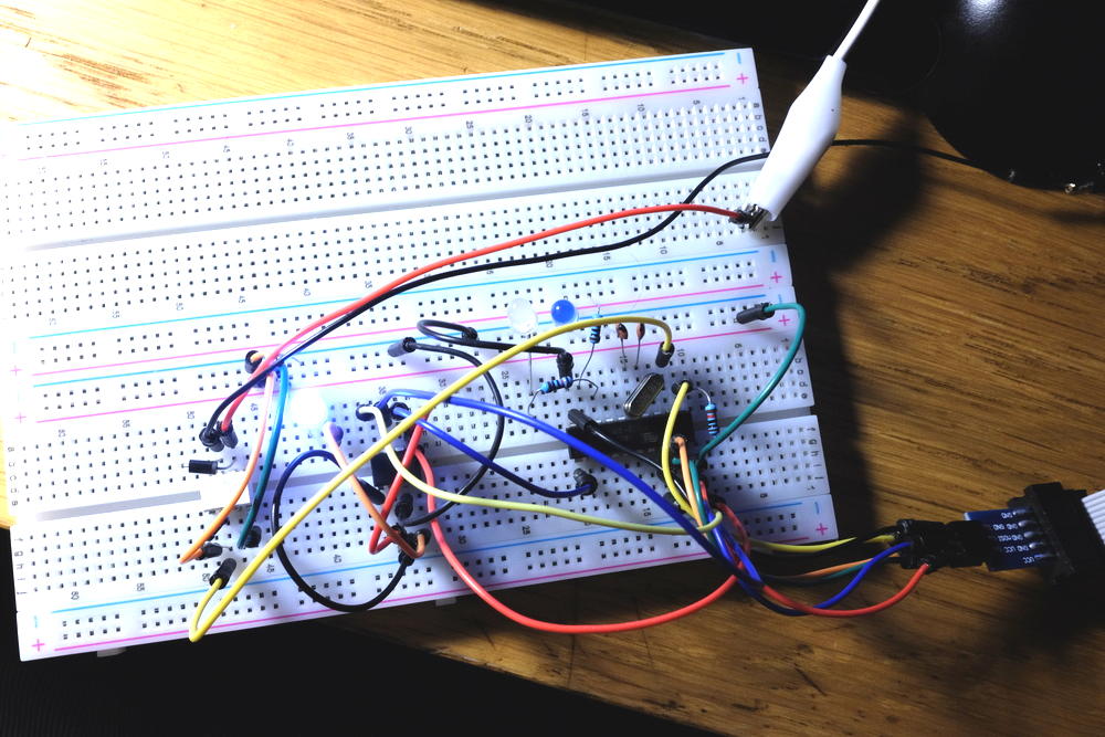
Next up: schematic and board design.
new blog
Initially I started this blog under the name "white noise fashion tips", but I was struggling to write anything for it. I realized that the person I was trying to present just wasn't me.
I'm not cool electronic musician slash programmer slash synth-DIY maker.
I'm just a guy that's trying to put a positive spin on him sitting alone at home doing stuff. I'm a hobbyist.
And there are things that I think are cool, but I don't really enjoy doing them ("hey, it would be cool to write a whole album on DS-10!"). And I've got to stop doing them.
So in the future I will try to put here stuff I'm working on with some comments, trying my best not to pretend to be a some sort of other persona.
Wish me luck.